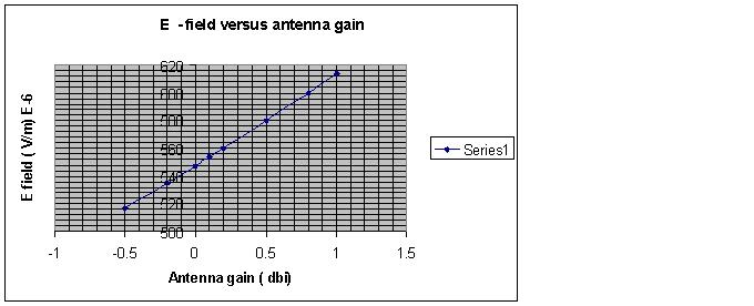
Once the antenna factor of an antenna is known ( either given by the manufacturer or calculated), the open circuit voltage at the terminals of the antenna can be calculated ( technique presented under the antenna factor post) if the E field is known ( and the polarization is correct). This post provides a graph that shows the variation of the E-field at a fixed distance using a fixed power. The calculations are such that any of these parameters can be varied and the E – field can be calculated. For more information or custom calculations please contact us using the email contact through the SPG website. Obviously from a curve such as this one can generate a curve fitting expression and use it to calculate the result for other parameters. The parameters used for this calculation was a distance of 1 km and a power of 100mW into the antenna. The input impedance is 50 Ohm.
Monthly Archives: September 2014
A simple expression for generating static standing waves.
In some cases it may be interesting to generate standing waves for visualization or analysis/synthesis of reflection on media or otherwise. A simple expression is presented that allows the user to plot standing waves with various reflection coefficients, amplitudes and wave numbers. The three tools we have used to do this are, GNUPLOT ( available free on the web), MATLAB and MS Excel. Please view this expression at http://www.signalprop.biz/standing_waves.pdf
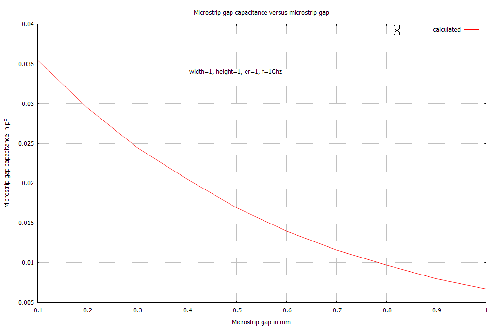
Micro-strip gap capacitance – calculated data
There are a number of models of microstrip gap capacitance in the literature. Using an accurate model of the gap capacitance developed by Kirschning, Jansen and Koster ( 1983 MTT-S Digest, pp 495 – 497) a script was used to calculate the series gap capacitance with respect to the gap. The microstrip parameters used were: width of both microstrips=1mm, height of the microstrip above the ground plane = 1mm, dielectric constant = 4.0 and at a frequency of 1Ghz. The results are presented below in graphical form. For more details and information on this topic and others please visit http://www.signalpro.biz.
Flicker noise ( 1/f noise) in MOSFETs
1/f noise in MOSFETs is a subject for continual study. Multiple noise models have been derived and studied. Each of these have some advantages and disadvantages. At Signal Processing Group Inc.we have used a simple model of 1/f MOSFET noise for some time. It has served its purpose in allowing us to at least estimate the 1/f noise for our design purposes. By using some kind of thumb rule, most appropriate to a particular design it is quite possible to use this model effectively. Interested readers are invited to read a brief paper on this subject released by a SPG technical team. Please click on the free papers… link on the SPG website.


