Microstrip ( or transmission lines) are used extensively in high frequency design of MMICs or PCB level circuits. In many cases it is simpler just to use a piece of microstrip as an inductance or a capacitance. ( Especially in microwave design). However we need to calculate what the microstrip dimensions should be to realize an inductor or a capacitor or both. ( There is much more information in the second edition of the forthcoming book on VSWR and matching techniques for the interested reader). Here then are the expressions for these types of structures:
XL = reactance of an inductive line = XL= ZoSin( 2*pi*length/lambdag). From this expression one can extract what the length should be as well. Here length is the length of the microstrip ( generally higher resistance e.g 100 Ohms), lambdag = wavelength in air/square root ( relative permittivity) also known as guide wavelength in some texts. Zo is the characteristic impedance of the microstrip line.
Capacitors can also be realized by microstrip structures. In this case the susceptance is given by:
B = (1/Zo)Sin2.0*pi*length/lambda. It should be noted that the line lengths for a capacitance are usually short and of low impedance.
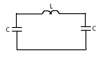
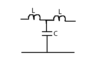
In each of these structures there are accompanying parasitic elements also, In the case of an inductance there are parasitic capacitors at the two ends. forming a pi circuit, See the diagrams below. In the case of a capacitor there are series inductances in its leads,
Please see the reference on these expressions: Foundations of Interconnect and microstrip design by T.C Edwards and M.B Steer. John Wiley and Sons LTD, publisher.
For more and other interesting information and articles visit our website.